 Sideway
BICK BLOG from Sideway
Sideway
BICK BLOG from Sideway
|
Link:http://output.to/sideway/default.asp?qno=140600017 1D Element Finite Element AnalysisOne dimensional linear element can be used to analysis structural pin jointed problems. One Dimensional Linear Element: in 2D Frame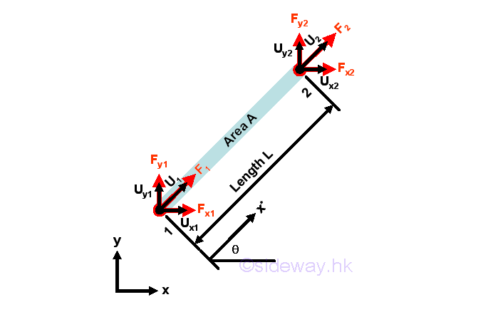
ElementIn an 2D environment, a typical bar element of length L and cross-sectional area A is assumed to be oriented at an angle θ anticlockwise from x-axis. The forces acting upon the bar element, which can be expressed as an element vector, can be decomposited such that forces between each element can react to each other. 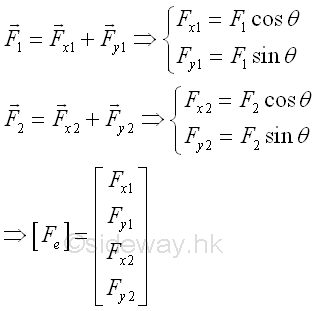
The displacements of the nodes of the bar element, which can be expressed as an element vector, can be decomposited and expressed in terms of decomposited elements such that displacements due to the bar element can be connected with other elements. 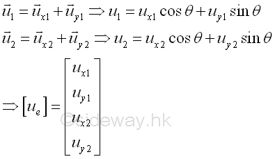
Shape Function or Interpolation FunctionFor a two-node linear element, the linear displacement function can be assumed to be a linear function of x* along the axial direction of the element That is 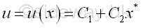
Similar to other boundary problems, this trial displacement function for the bar must satisfy the boundary displacement conditions at two nodes. That is 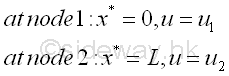
The displacement is therefore equal to 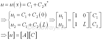
where [u] is the displacement vector of the element, [A] is a 'coordinate matrix', and [C] is the constant vector. The constant matrix is therefore equal to 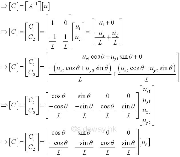
The displacement function and shape function are therefore equal to 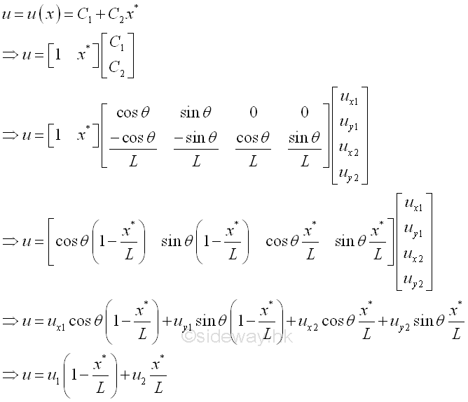
The Material Law or Constitutive EquationsOnce the choice of shape functions is fixed, the type of the finite element is also determined. The finite element should also follow the law of material, that is the stress-strain relationships. The strain in a bar element is given by 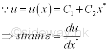
The strain of the element is therefore equal to 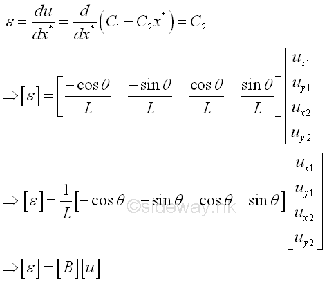
Where [B] is the strain displacement dimension matrix. Since the bar element is under uniaxial load, the stress in a bar element is given by 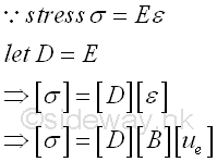
Where [D] is the material property or stress-strain matrix and is equal to the Young's modulus E for a uniaxial load. The stress is then expressed in terms of displacement also. The Element Stiffness MatrixForce Equilibrium ApproachSince the element is in equilibrium, the resultant force acting upon the element should be equal to zero. or forces act on the element is equal and opposite. Imply 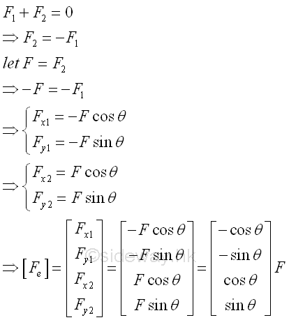
The element force vector can also be expressed in terms of the strain displacement dimension matrix [B], imply 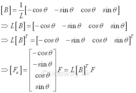
Since the element is under an uniaxial load F, the stress in the element is equal to, 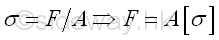
Therefore the element force vector can further be expressed in terms of displacement, 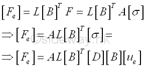
Therefore the element force vector can be expressed in form of stiffness times displacement, 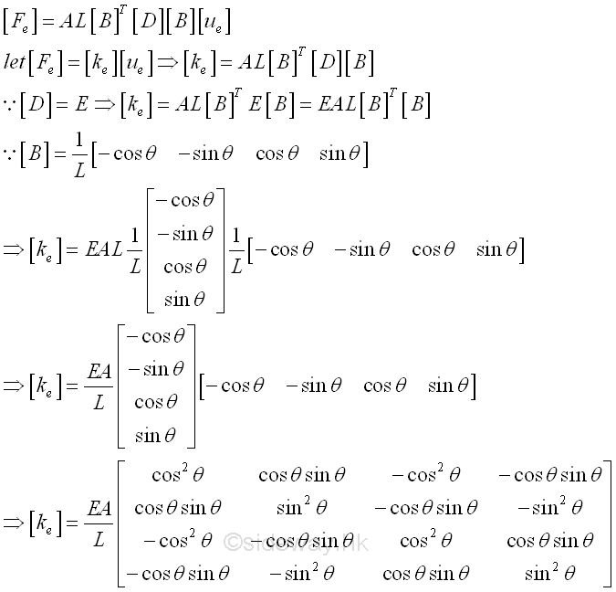
and the element stiffness matrix is a symmetric matrix. Minimum Total Potential Energy ApproachBy neglecting the body weight of the bar, the total potential enegy of the element is, 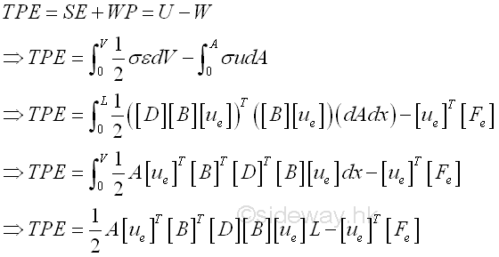
By the principle of minimum total potential energy, the differential of total potential energy (TPE) with respect to the displacement [Ue] must be zero, imply, 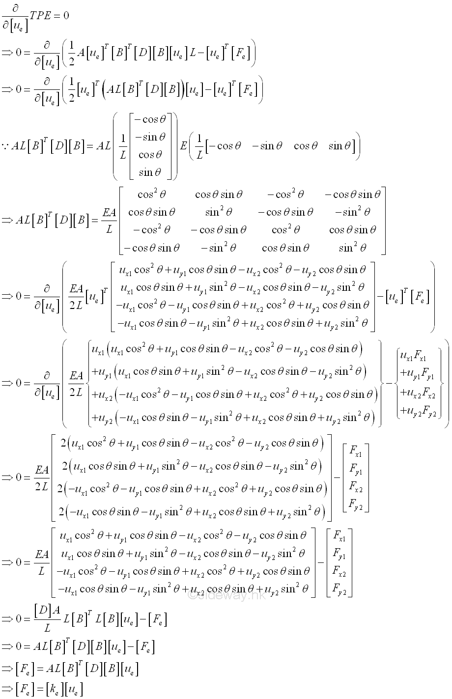
One Dimensional Linear Element: Example in 2D FrameConsider a simple system with 3 elements of same material of Young's modulus E, length L and area A. Three elements are connected by hinges. Three elements are arranged in an equilateral triangle shape, with one end of element 1 is fixed to a wall and the other end of element 1 is supported by a roller, while there is an applied load F applied to the top hinge of the triangular structure. 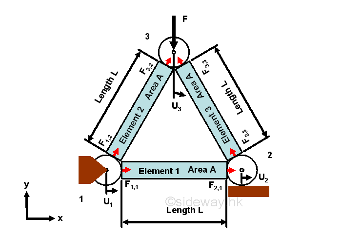
Element-wise Force-Displacement EquationElement-wise Force-Displacement Equations for each element of the system can be constructed accordingly. Besides the length, cross-sectional area, and material property of each element, the orientation of the element is another important property of the element. For consistency, positive angle are used to orient the element at an angle θ anticlockwise from x-axis. 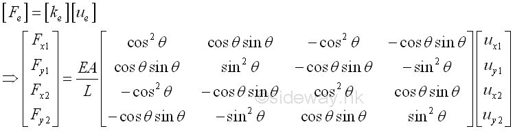
Element 1For element 1, that is from node 1 to node 2, angle of orientation is 0 degree, length=L, area=A, Young's modulus=E, imply 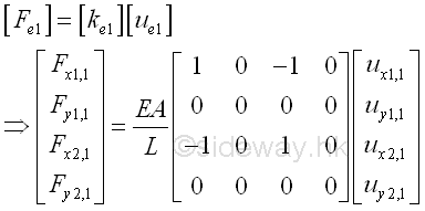
Element 2For element 2, that is from node 1 to node 3, angle of orientation is 60 degree, length=L, area=A, Young's modulus=E, imply 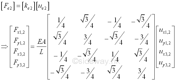
Element 3For element 3, that is from node 2 to node 3, angle of orientation is 120 degree, length=L, area=A, Young's modulus=E, imply 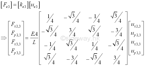
Node-Wise Force-Displacement EquationFor both the force equilibrium approach or the minimum potential energy approach, all element-wise force-displacement equations are in equilibrium. Since the displacement of any node in the system is same for every element attached to the node, the element-wise displacements of nodes are the same and with common displacement for every element connected. However, the considered element-wise force is not common force for every element connected to the node, and the forces for each element, in general, are usually difference in magnitude and direction. All element forces at a particular node are used to create the corresponding work potential for all element connected to the node, therefore the sum of all element forces are equal to induced forces due to the displacements of all elements connect to the node. 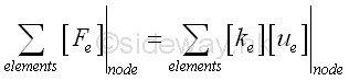
node 1Two elements, 1 and 2, are connected at node 1. The sum of element forces at node 1 is equal to the sum of induced forces due to the displacements of all elements, 1 and 2, connect to the node 1. 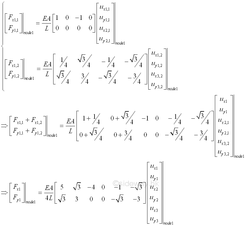
node 2Two elements, 1 and 3, are connected at node 2. The sum of element forces at node 2 is equal to the sum of induced forces due to the displacements of all elements, 1 and 3, connect to the node 2. 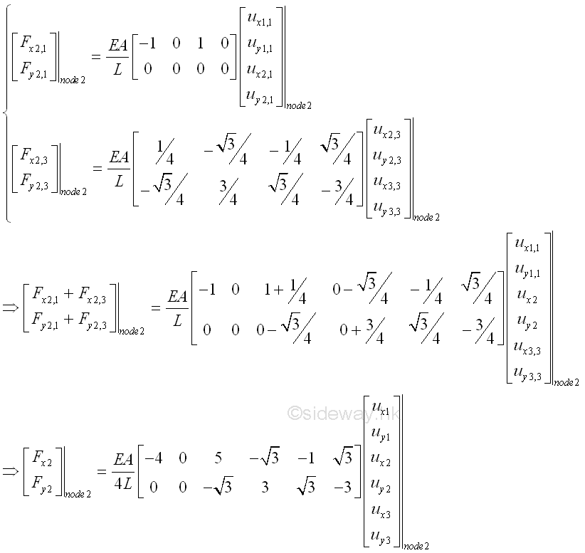
node 3Two elements, 2 and 3, are connected at node 3. The sum of element forces at node 3 is equal to the sum of induced forces due to the displacements of all elements, 2 and 3, connect to the node 3. 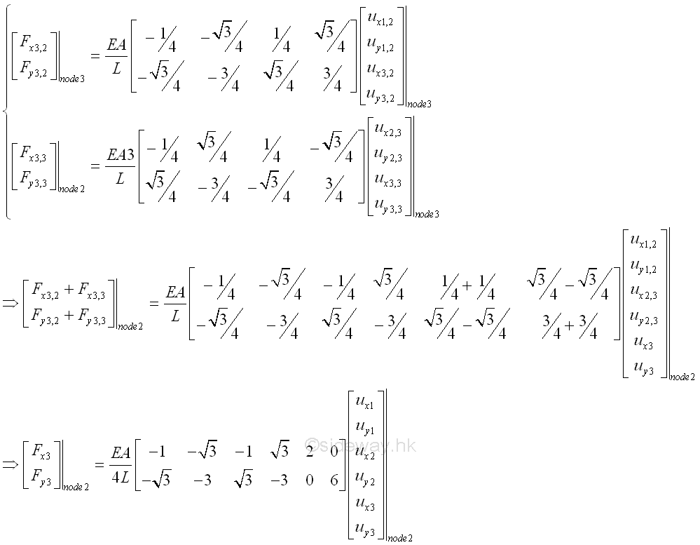
Global Force-Displacement EquationAll element forces can be assembled as a global system of equations in form of global matrices which contains all the nodes. 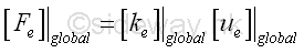
That is 2*3 element forces, 2*3 displacements at 3 nodes, and stiffness matrix is (2*3) by (2*3). imply 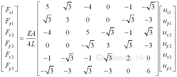
and the global stiffness matrix is a symmetric matrix. Boundary Conditions and External LoadsSince the system of elements is in equilibrium, both forces and displacement at node should be in equilibrium. In other words, The displacements of nodes in the global force-displacement equations should be same as the allowable boundary conditions, and the element forces exerted on nodes should be equal to the external load acted upon the nodes accordingly. That is,
Global Conditionalized Force-Displacement EquationSubstitute all boundary conditions and external loads into the global force-displacement equation. That is 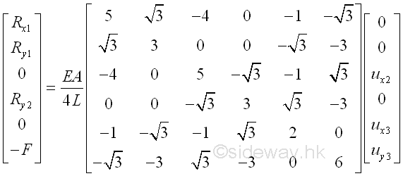
Force-Displacement Equation SolvingThere are 6 force-displacement equations and 6 unknowns, therefore the global force-displacement equation can be solved. Since the most interested unknown variables are displacements, the global force-displacement equation can be divided into two parts. Force-displacement equations with unknown displacement variables and force-displacement equations with unknown reaction variables. For force-displacement equations with unknown reaction variables which also depending on unknown displacement variables. 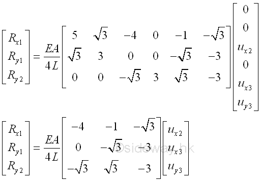
For force-displacement equations with unknown displacement variables 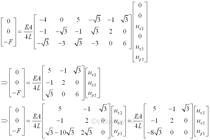
Unknown displacement variables are therefore equal to 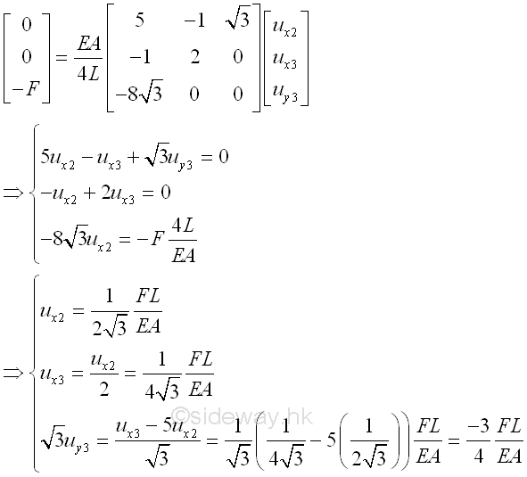
Unknown reaction variables are therefore equal to 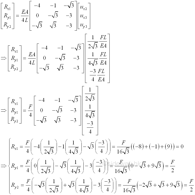
. |
Sideway BICK Blog 30/06 |
||||||||||||||||||||||||||||||||||||||||||||||||||||||||||||||||||||||||||||||||||||||||||||||||||||||||||||||||||||||||||||||

