 Sideway
BICK BLOG from Sideway
Sideway
BICK BLOG from Sideway
|
Link:http://output.to/sideway/default.asp?qno=140600016 Elements Finite Element AnalysisOne dimensional linear element can be used to analysis structural pin jointed problems. One Dimensional Linear Element: Strain and Stress Approach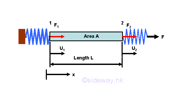
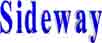
Considering a bar, of length L and cross sectional area A, is subjected to a axial spring loads. Let forces at 1 and 2 are equal to F1 and F2 and the displacements of the bar due to the applied load F is u1 and u2 respectively. Assuming the material of the bar is linear elastic, then the stress-strain relationships of the bar is equal to 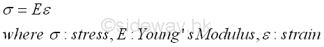
Stress is defined as the average force per unit area. That is 
Young's modulus, E or the elastic modulus, is a numerical value to describes the elastic properties of the material undergoing elastic deformation. The unit of Young's modulus is also Nm-2 since strain does not have any unit. Strain is defined as the ratio of total deformation over the original dimension of the bar. That is 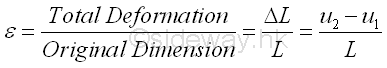
Subsitute equations of stress and strain into the stress-strain relationships of the bar, and a force-deformation relationship expressed in terms of force and displacement is obtained. 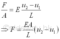
When considering the bar as an individual object, forces, F1 and F2 at both ends of the bar can be expressed analytically as following by assuming a fixed end opposite to the interested force with one consistent coordinate system. 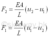
The bar can also considered as an element of the system, in which both forces F1 and F2 and displacement u1 and u2 are expressed as one individual element. This can be done by expressing the two force equations in matrix form as 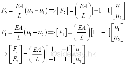
And expressed concisely in an element-wise matrix form which can be used in numerical method as 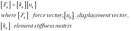
One Dimensional Linear Element: Example of a 2 elements systemConsider a simple system with 2 elements of same material of Young's modulus E, length L and area A. Two elements are connected by a hinge, with one end of element 1 is fixed to a wall, while one end of element 2 is under an applied load F. 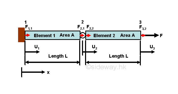
Using the standard coordinate system, the force-displacement equations for elements 1 and 2 are 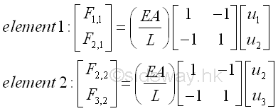
The two force-displacement equations for elements are only elemental equations of the 2 element sytem. Numerically, the force-displacement equations can be combined together to form a bigger system matrix form. 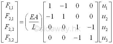
As node 2 is a common point for force F2,1 and F2,2, forces acting on node 2 can further be combined by assembling or grouping the two related force and displacement equations into one equation only. The global matrix form can be reduced to have equations for 3 nodes only. 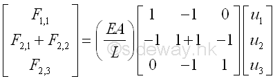
The 3 equations are used to represent the mechanical properties at the 3 nodes. In other words, the magnitudes of force and displacement global element matrix are bounded by the mechanical properties of the physical system. At node 1, the displacement u1 is equal to zero, and the reaction force F1,1 is unknown and is equal to the total reaction force F1 at node 1. At node 2, the displacement u2 is unknown, and the resultant force F2,1+F2,2 is equal to zero since the total reaction force F2 at node 2 is in equilibrium. At node 3, the displacement u3 is unknown, and the resultant force F3,2 is equal to the applied load F, the total reaction force F3 at node 3. That is 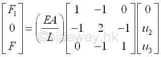
Since there are three force and displacement equations and three unknown, the force and displacement equations can solved. 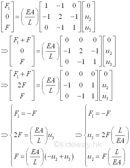
One Dimensional Linear Element: Energy Approach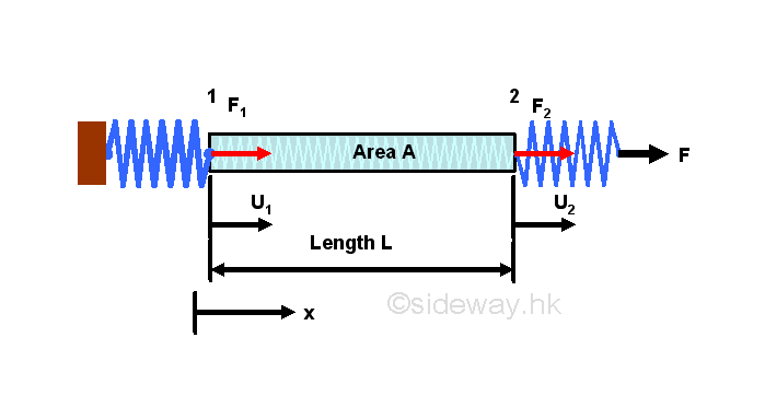
Strain EnergyThe force analytical approach to derive the element stiffness matrix gives an fundamental idea on the numerical method in finite element analysis. An energy approach is an alternative way to derive the element stiffness matrix. The elastic deformation of the bar under applied load reacts like a mechanical spring, strain energy is stored by the system when undergoing deformation. The strain energy, U, per unit volume is equal to 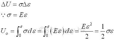
Since displacement is a function of x, local x, along x direction, strain energy for the bar of length L with constant sectional area is equal to 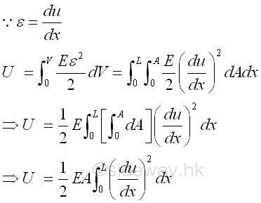
Displacement FunctionFor a two-node linear element, the linear displacement function can be assumed to be a linear function of x. That is 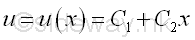
Similar to other boundary problems, this trial displacement function for the bar must satisfy the boundary displacement conditions at two nodes. That is 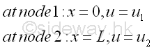
The displacement function is therefore equal to 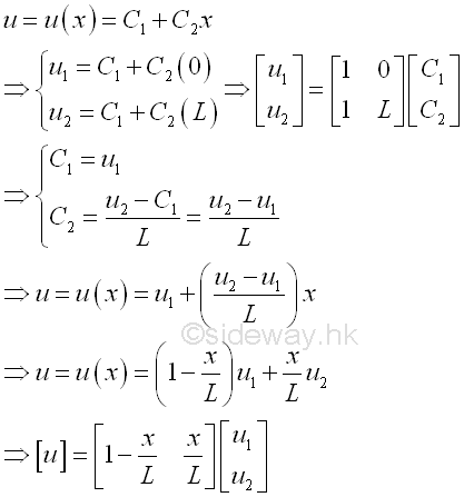
The displacement function can therefore be used to describe the displacement of each particle along the bar. The functions that used to multiply the nodal displacements u1 and u2 are therefore called shape functions or interpolation functions. The differentiation of the displacement function is equal to 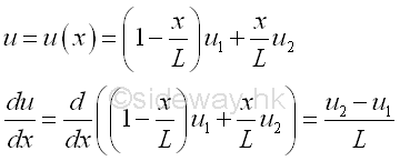
Total Potential EnergyThe total strain energy stored in the bar element is therefore equal to 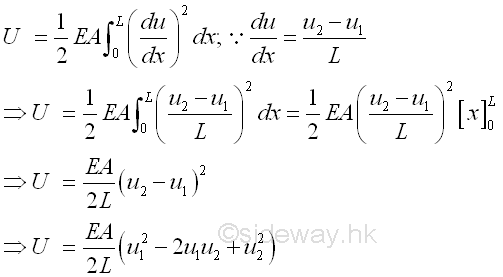
Work done is defined as the applied force times the travelled distance along the direction of the applied force. That is 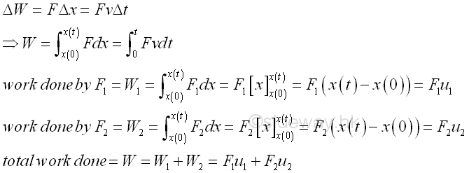
Work potential is defined as the negative of the work done by the external forces acting on the structure. Since the deformed state of the bar element attained upon the application of applied loads is in the equilibrium state, the total potential energy (TPE) or potential energy (PE) of the bar element is defined as the sum of the strain energy (SE) and the work potential (WP). That is 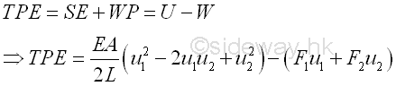
Principle of Minimum Total Potential EnergyThe total potential energy (TPE) equation provides a relationship between the applied forces and displacements of element nodes. The deformation due to the applied forces are in static equilibrium. From the principle of minimum total potential energy, a conservative system is in equilibrium if the total potential energy of the system is stationary. The principle implies that the conservative system will only attain a unique deformation at an equilibrium point to achieve the equilibrium state with respect to the independent variables for the given forces. The unique deformation corresponds to the extreme value of the minimum total potential energy, the equilibrium of the system is stable if the total potential energy of the conservative system is a minimum. Since the external applied forces is the only external source of energy included in the total potential, the virtual infinitesimal change in total potential with respect to a virtual infinitesimal change of the independent variable corresponding to an infinitesimal physical change of the conservative system should be equal to zero. That is 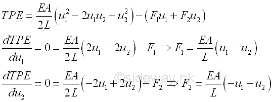
Similarly, the bar can also considered as an element of the system, in which both forces F1 and F2 and displacement u1 and u2 are expressed as one individual element. This can be done by expressing the two force equations in matrix form as the force analysis approach before. That is
. |
Sideway BICK Blog 28/06 |
||||||||||||||||||||||||||||||||||||||||||||||||||||||||||||||||||||||||||||||||||||||||||||||||||||||||||||||||||||||||||||||

