 Sideway
BICK BLOG from Sideway
Sideway
BICK BLOG from Sideway
|
Link:http://output.to/sideway/default.asp?qno=120200071 Planar Truss Simple Planar TrussStability:In truss design, one of the main concern is the stability of the structure. Because truss members are assumed to be connected by frictionless pin, the bending moment between members is negligible and truss members can rotate freely about the joint. Besides the need of proper constraints to maintain the stability of a truss, any unstable arrangement of members should also be eliminated. For example, the top storey is unstable and the truss will colllapse when appling force Q. 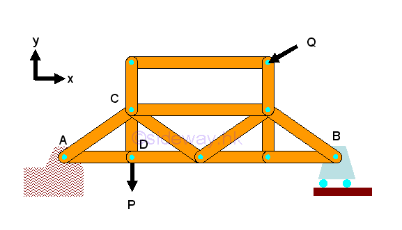
If a simple truss is made of four members connected by pins, the truss will be easily deformed by appling a load at its upper corner. 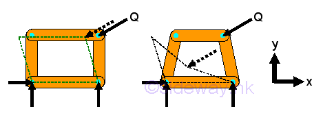
However, If the member of a simple truss is made of three members connected by pins, the truss will be deformed slightly only when appling a load at its upper corner. The geometrical shape of the truss remains unchange under loading, the only possible deformation is the dimensional changes in the length of the truss member due to the applied load. This type of truss is so called rigid truss because the truss will not collapse under loading. 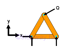
The truss does not collapse because the motion of connection pin joint is interlocked by fixing the other ends of the two connected truss members. By applying similar strategy, a larger rigid truss can be built by adding two truss members to the existing joints of the basic simple truss and the other ends are then connected by a frictionless pin to form a new joint which should not lie beween the two joining joints in the form of a straight line. In general, new members are usually joined to the neighborhood joints belong to the same truss member to form a new triangle of the truss. However, they can also be attached to two seperated joints belong to two different truss members. Although the four truss members usually form a triangle, sometimes they are not. 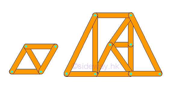
In general, a rigid truss can be constructed by starting with a basic triangular truss with three members and three joints. Therefore, for constructing a rigid truss, two more members and one more joint are added to the rigid truss. Mathematically, the total number of member m is equal to 2 times the total number of joints minus 3, i.e. m=2n-3. In other words, the structure of a simple rigid truss alway have the equation equal to m=2n-3. Determinacy:Since all truss members are two force member, each member has only one unknown force. The total number of unknown force is equal to the total number of truss member, M. Assume the total number of unknown reactions in a two dimensional structure is R. Therefore the number of unknowns for a constrained truss is equal to number of truss members, M plus number of reactions, R, i.e. total number of unknowns = M+R. At each joint, there is no couple and two equilibrium equations of rectangular componenets can be formulated only. Therefore the number of equilibrium equations for a truss with number of joint N is 2 times the number of joints. i.e. total number of equilibrium equations = 2 N. Although there are three more equilibrium equations can be written from the free body diagram of truss since the truss is in static equilibrium, these three equilibrium equations are not independent equation. These static equilibrium equations can only provide additional relationship between external forces. A truss is statically determinate, only when the number of unknowns is equal to the number of equilibrium equations, i.e. M+R=2N. For a two dimensional completely constrained structure, the total number of reactions, R is equal to 3. The equation can be rewritten as M+3=2N or M=2N-3, which is same as the stability requirement, m=2n-3. Therefore a stable truss is statically determinate only if the truss is properly constructured. When an additional member is added to a stable truss, the truss becomes over rigid and is statically indeterminate. For example. additional diagonal of a "X" crossed panel in a truss. 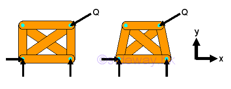
Forces Analysis by Method of Joints:The method of joints is a general method used to calculate forces in trusses. Since all forces passes through the truss joints, there is no couple at the truss joints and moment equilibrium equation is not necessary to be considered in the force analysis at joint. However moment equilibrium equation still can be used on the static analysis of a truss. For example, a simple truss bridge with concentrated load P. 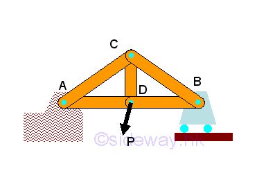
The free body diagram of the truss bridge is 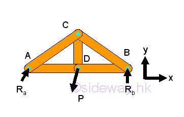
After setting up the three equilibrium equations for the truss structure, all reactions can be determined accordingly. In order to analyze the members in truss, corresponding free body diagrams of joints and members are constructed by dis-assembly the truss structure into component parts, imply 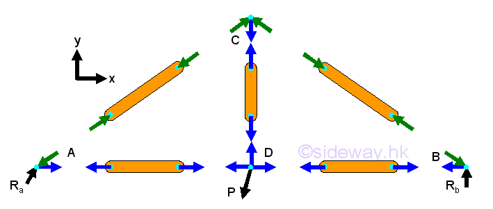
For a two force member, the force in the truss member is either tensile or compressive force only. Since all forces are acting on truss joint pins only, the two forces at the two end joints of a truss member should be equal in magnitude and line of action but opposite in sense when the truss is in equilibrium. The force in the member can be assumed either tensile or compressive, the sense of the direction will confirm whether the assumption is correct or not. And by Newton's third law, the action and reaction forces between a joint pin and a truss member are always equal and opposite. Therefore at each joint, every connected truss member will exert an force of equal in magnitude and line of action, and opposite in sense on the joint pin. Since the truss is in equilibrium, the resultant force of all forces including truss reactions, applying loads and reactions acting on the joint pin is equal to zero. Assuming all positive vectors in scalar, the two equilibruim equations on each joint is 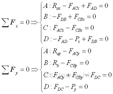
By making use of the truss trigonometry, eight unknowns can then be expressed into eight force equilibrium equations, imply 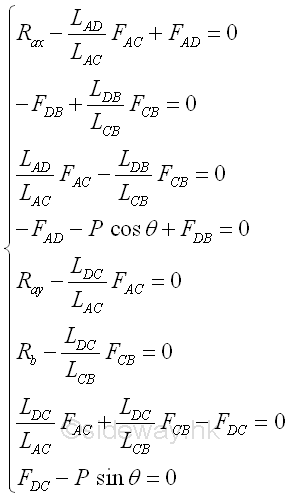
Link:http://output.to/sideway/default.asp?qno=120200072 Planar Truss Simple Planar TrussDetermination of Forces in Trusses :
Eight equations with eight unknowns imply the forces in the truss is statically determinate. There are a number of way to determine forces in trusses by the method of joints. Solving Equilibrium Equations:In general the eight equilibrium equations can be solved mathematically. The eight equilibrium equations can be divided into two groups, i.e. with external reactions and without external reaction. Imply 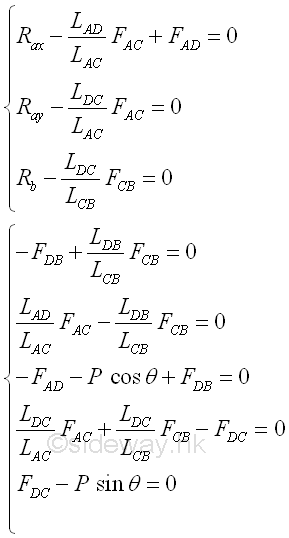
Focusing on the group without external reaction, five equations with five unknowns imply the forces in the truss member can be determinated. 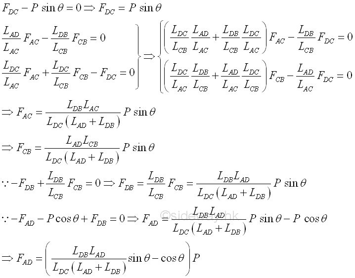
The external reaction can then be determined. Imply 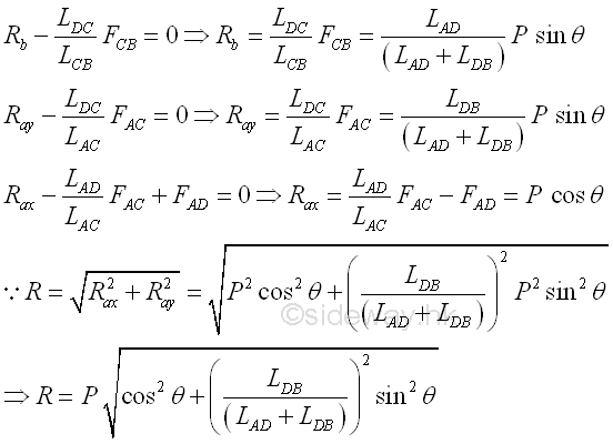
Solving Static Equilibrium:Or unknown forces can also be determined by making use of the mechanical static equilibrium state. When the completely constrained truss is in static equilibrium, all the unknown reactions can be determined. Imply 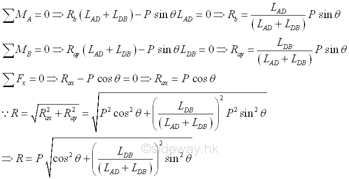
Since a simple truss is constructed by adding two truss members to form a new joint, in general, a joint involving two unknown forces from two truss members can always be found. For a statically determinate truss, the unknown forces in the truss can always be determined by the static equilibrium of the joint pin connecting to two truss members. Therefore starting with a joint with two truss members, i.e. joint pin A. Imply 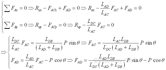
After two unknowns are determined, the unknowns of the two neighborhood joints will be reduced by one. Applying the same strategy to select neighborhood joints with two unknowns, i.e. joint pin D. Imply 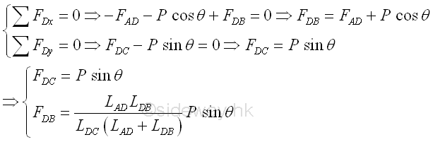
Repeating the procedure untill all unknown are determined. All possible joints with two unknowns i.e. joint pins B and C can be used. It can be either to continue selecting the neighborhood joint or to start with other possible joint from other ends. Use joint C, Imply 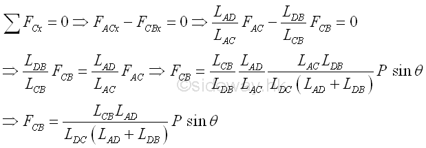
Solving Force Vector Diagram:Sometimes, the unkonwn forces can be determined using graphical methods through the determination of force vector by constructing the force vector diagram at each joint. Starting the joint pin with known force, so that all force vector diagram can be scaled to a known value, i.e joint pin D, Although joint pin D is constained in y dimension only, joint pin D is still a good choice. Besides the equilibrium force vector diagram should always be draw in one direction for all joint pins, i.e. counter-clockwise direction imply 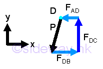
Continuing the joint pin with known dimension, which is fully constrained by the known force before so that all force vector diagram can be scaled to a known value, i.e joint pin C, imply 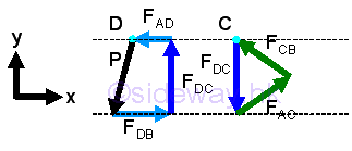
Continuing the joint pin with known dimension, which is fully constrained by the known force before so that all force vector diagram can be scaled to a known value, i.e joint pin B. The vector diagram of Joint pin A is not fully constrained because the unknown reaction R is a vector of two rectangular components. imply 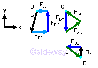
Since FDB is constrained, the unconstrained force vectors at point D can be fixed also. imply 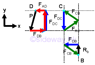
Continuing the joint pin with known dimension, which is fully constrained by the known force before so that all force vector diagram can be scaled to a known value, i.e joint pin A. imply 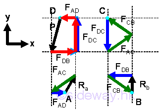
The force vector diagtram can be joined to form a single diagram, known as Maxwell's diagram. This single diagram can give a more general idea on the characteristic of the trusses, imply 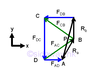
|
Sideway BICK Blog 26/02 |
||||||||||||||||||||||||||||||||||||||||||||||||||||||||||||||||||||||||||||||||||||||||||||||||||||||||||||||||||||||||||||||

