 Sideway
BICK BLOG from Sideway
|
Link:http://output.to/sideway/default.asp?qno=120800015 Shape FAQ - Microsoft PowerPoint Microsoft PowerPointFAQ.
Link:http://output.to/sideway/default.asp?qno=120800017 Simple Geometry 2 Free Form ShapesShape
Link:http://output.to/sideway/default.asp?qno=120800018 Flat Belt & Vee Belt Applications of Friction ForcesFrictional forces are also found in many common practical tools and machines with rotating members. Flat BeltsFlat belt is commonly used in a belt drive transmission system to transmit power from the power drive to the machines. Power is transmitted from the driving pulley through the generated friction force acting on the belt to the driven pulley at which load is driven by the friction force generated by the belt on the driven pulley. For example, a flat belt is wrapped arround a fixed cylindrical drum with angle of wrap β. Because of the presence of friction force between the belt and the drum, the tension T2 on the right is greater than the tension T1 on the left when the belt has impending motion to the right. 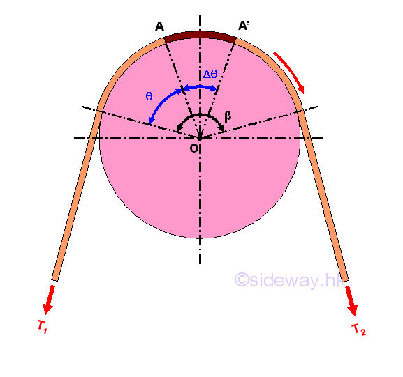
Consider forces acting on a small elemental segment of the belt A-A', imply 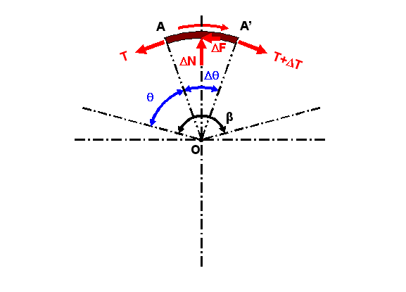
Since the motion of the belt is impending, the elemental segment of the belt is in static equilibrium also. Forces acting on the elemental belt segment are the two tension forces T and T+ΔT, the normal reaction force ΔN of the drum and the reactive friction force ΔF between the contact surfaces of the belt and drum. When the elemental segment is very small and the motion is impending, the horizontal components of the elemental belt tensions are also balanced by the static friction force ΔF. The vertical components of the elemental belt tensions on both sides acting on the drum is reacted by the normal reaction force ΔN. By equilibrium equations 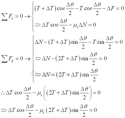
When the angle Δc of the elemental belt segment approaches zero, the magnitudes of normal force ΔN, static friction force ΔF and belt tension difference ΔT approach zero also. And the difference between the tensions T1 and T2 , can be obtained by adding all tension differences ΔT between the two sides of the belt segment along the contact part. Since the tension difference ΔT approaches zeros when the angle Δθ approaching zero, the magnitude of tension difference ΔT when the angle Δθ approaching zero can be determined by dividing the equation with Δθ. Imply. 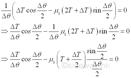
By taking the limit as the angle Δθ approaches zero, the value of cosine (Δθ/2) approaches 1, the value of ΔT/2 approaches 0 and the value of sine (Δθ/2)/Δθ/2 approaches 1 when the angle is expressed in radian. Imply 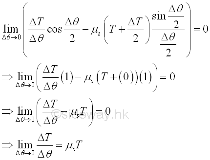
Since the derivative is defined as the limit of the ΔT/Δθ, the relationship between the two tension forces T1 and T2 acting on belt can be determined by integration. Imply. 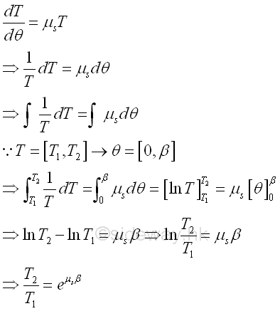
Since the ratio of tension forces is a function of the coefficient of static friction μs,.the equation can be applied to other application, like rope wrapped around a round post, brake shoe on a circular drum. When slipping occurs between the belt and the drum, the coefficient of static friction gs should be replaced by the coefficient of kinetic friction gk . Besides, the ratio of tension forces is also a function of the contact surface in terms of angle β expressed in radian, the angle β can be larger than 2 π. Vee BeltsIn practical belt drive system, a Vee belt is often used. The V-belt with trapezoidal cross-section is mounted in the mating groove of the pulley. The dimension of the V-shaped belt is such that there is alway a gap between the belt and the bottom of the groove and the belt will wedge into the groove as the tension force increase. Since there is no surface contact between the belt and the bottom of the groove, the only contact betwee the belt and the pulley is the sides of the belt and the sides of the groove. For example, a v-belt of wedge angle \, is wrapped arround a fixed cylindrical pulley in the groove of groove angle α, with angle of wrap ]. Because of the presence of friction force between the belt and the drum, the tension T2 on the right is greater than the tension T1 on the left when the belt has impending motion to the right. 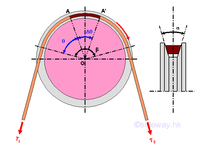
Consider forces acting on a small elemental segment of the belt A-A', imply 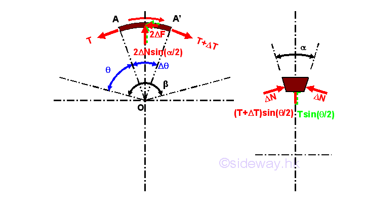
Since the motion of the belt is impending, the elemental segment of the belt is in static equilibrium also. Forces acting on the elemental belt segment are the two tension forces T and T+ΔT, the two normal reaction forces 2xΔN of the groove and the two reactive friction forces 2xΔF between the contact surfaces of the belt and groove of the pulley. When the elemental segment is very small and the motion is impending, the horizontal components of the elemental belt tensions are also balanced by the two static friction forces 2xΔF. The vertical components of the elemental belt tensions on both sides acting on the pulley is reacted by the vertical components of the two normal reaction forces 2xΔN. While the horizontal components, perpendicular to the tension forces, of the two normal reaction forces ΔN will balance each other. By equilibrium equations 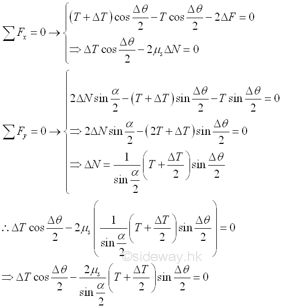
When the angle Δc of the elemental belt segment approaches zero, the magnitudes of normal force ΔN, static friction force ΔF and belt tension difference ΔT approach zero also. And the difference between the tensions T1 and T2 , can be obtained by adding all tension differences ΔT between the two sides of the belt segment along the contact part. Since the tension difference ΔT approaches zeros when the angle Δθ approaching zero, the magnitude of tension difference ΔT when the angle Δθ approaching zero can be determined by dividing the equation with Δθ. Imply. 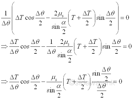
By taking the limit as the angle Δθ approaches zero, the value of cosine (Δθ/2) approaches 1, the value of ΔT/2 approaches 0 and the value of sine (Δθ/2)/Δθ/2 approaches 1 when the angle is expressed in radian. Imply 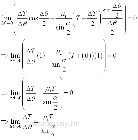
Since the derivative is defined as the limit of the ΔT/Δθ, the relationship between the two tension forces T1 and T2 acting on belt can be determined by integration. Imply. 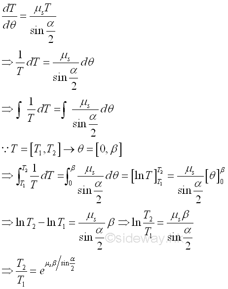
|
Sideway BICK Blog 17/08 |
||||||||||||||||||||||||||||||||||||||||||||||||||||||||||||||||||||||||||||||||||||||||||||||||||||||||||||||||||||||||||||||
