 Sideway
BICK BLOG from Sideway
|
Link:http://output.to/sideway/default.asp?qno=120800024 Shear and Bending Moment Diagrams of Distributed Applied Loads & Concentrated Couples Internal Forces in BeamsThe shearing forces and bending moments in a statically determinate beam can be determined by the equilibrium equations. Using the standard convention, the distribution of internal forces in a beam can be represented graphically by plotting the values of shear or bending moment against the distance from one end of the beam. Besides concentrated applied loads and moments, the applied force can also be distributed applied loads and moments, and concentrated couples. Shear and Bending Moment DiagramsInternal Forces in a Simply Supported Beam with Distributed Load
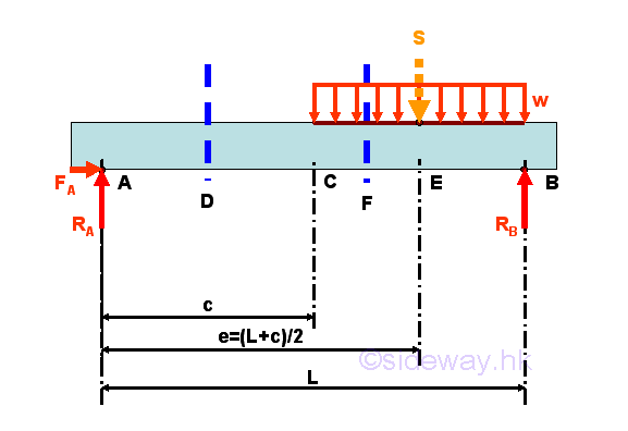
For example, consider a simply supported beam with a distributed load of w per unit length over length CB of the beam. The equivalent force for the distributed load can be represented by a force S acting at the middle point E of length CB on the beam, i.e. e=(L+c)/2. The free-body diagram of the entire beam is 
The reactions at the hinged and roller supports can be determined by the equilibrium equations. 
Internal forces can be determined by dividing the beam into two separated free body. Selecting a point D between A and C, i.e. A<D<C 
Consider the member section AD of length d, the internal forces at point D are 
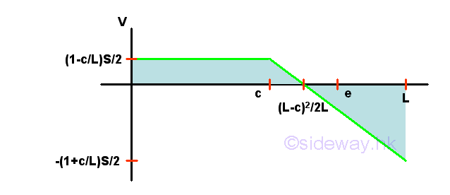
Point D is a random point between A and C. The shear force V is a constant and is equal to (1-c/L)S/2 between point A and point D. And bending moment M is a linear function of point D. Therefore bending moment M=0 at point A and bending moment M=(1-c/L)Sc/2 at point C. Selecting another point F between C and B, i.e. C<F<B 
Consider the member section AF of length L-F, the internal forces at point F are 
Point F is a random point between C and B. The shear force V is a linear function of point D.The shear force V=(1-c/L)S/2 at point C and the shear force V=(1-c/L)S/2-w(L-c)=-(1+c/L)S/2 at point B. Because of the moment due to the distributed load, the bending moment M is also a second degree function of point D. Therefore bending moment M=(1-c/L)Sc/2 at point C and bending moment M=(1-c/L)SL/2-w(L-c)^2/2=((L-c)-(L-c))S/2=0 at point B. However, the bending moment M is a curve of degree n between C and B, more data is needed to plot the bending moment curve between C and B. The curve of bending moment M between C and B can be rewritten as 
Therefore the bending moment M between C and B is always greater or equal to zero. The maximum bending moment M between C and B is 
And the bending moments M between C and B at typical points are 
similarly when the shear is equal to zero, the position of point F is 
Shear Diagramar Diagram
Bending Moment Diagram
Internal Forces in a Simply Supported Beam with Concentrated Load and Concentrated Moment
For example, consider a simply supported beam with a concentrated load and a concentrate moment by applying one applied force on the L shape plate which is fixed on around the middle of the beam. Since the applied force P is not directly acting on the beam body, the applied force P applied on the L shape will generated a concentrated force P and a concentrated moment MC at the mounting point of the L shape plate on the beam body. Through system of force transformation, the generated concentrated moment due to the applied force P at point C is 
The free-body diagram of the entire beam is 
The reactions at the hinged and roller supports can be determined by the equilibrium equations. 
Internal forces can be determined by dividing the beam into two separated free body. Selecting a point D between A and C, i.e. A<D<C 
Consider the member section AD of length d, the internal forces at point D are 
Point D is a random point between A and C. The shear force V is a constant and is equal to (1-h/L)P between point A and point C. And bending moment M is a linear function of point D. Therefore bending moment M=0 at point A and bending moment M=(1-h/L)Pc at point C. Selecting another point E between C and B, i.e. C<E<B 
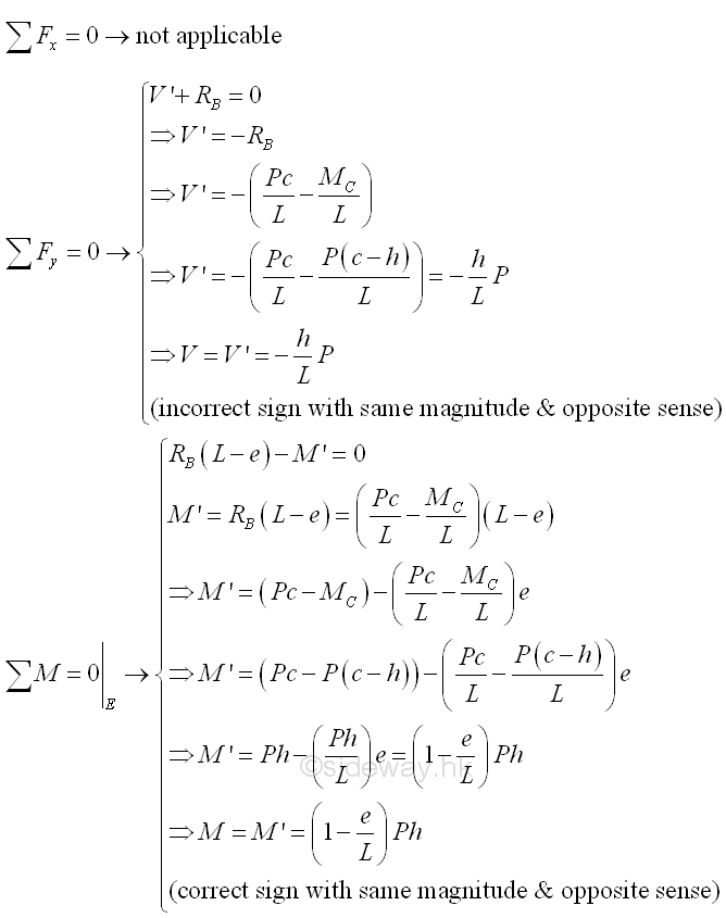
Consider the member section EB of length L-e, the internal forces at point E are 
Point E is a random point between C and B. The shear force V is a constant and is equal to -(h/L)P between point C and point B. And bending moment M is a linear function of point E. Therefore bending moment M=(1-c/L)Ph at point C and bending moment M=0 at point B. Shear Diagram
Bending Moment Diagram
Internal Forces in a Simply Supported Beam with a Concentrated Couple
For example, consider a simply supported beam with a concentrated couple by applying a couple, a pair of applied forces P on the S shape plate which is fixed on around the middle of the beam. Since the pair of applied forces P is not directly acting on the beam body, the pair of applied forces P applied on the L shape will generated a concentrated couple at the mounting point of the S shape plate on the beam body only. And the resultant force due the pair of the applied forces is equal to zero. Through system of force transformation, the generated concentrated moment due to the pair of applied force P at point C is 
The free-body diagram of the entire beam is 
The reactions at the hinged and roller supports can be determined by the equilibrium equations. 
Internal forces can be determined by dividing the beam into two separated free body. Selecting a point D between A and C, i.e. A<D<C 
Consider the member section AD of length d, the internal forces at point D are 
Point D is a random point between A and C. The shear force V is a constant and is equal to -2P(c-h)/L between point A and point C. And bending moment M is a linear function of point D. Therefore bending moment M=0 at point A and bending moment M=-2P(c-h)c/L at point C. Selecting another point E between C and B, i.e. C<E<B 
Consider the member section EB of length L-e, the internal forces at point E are 
Point E is a random point between C and B. The shear force V is a constant and is equal to -(2P(c-h))/L between point C and point B. And bending moment M is a linear function of point E. Therefore bending moment M=2P(c-h)(1-c/L) at point C and bending moment M=0 at point B. Shear Diagram
Bending Moment Diagram
|
Sideway BICK Blog 29/08 |
||||||||||||||||||||||||||||||||||||||||||||||||||||||||||||||||||||||||||||||||||||||||||||||||||||||||||||||||||||||||||||||

