MicroControllerArduinoArduino StartingArduino SetupArduino BlinkArduino Digital PinArduino Digital I/O |
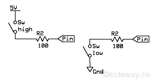
Arduino Digital I/ODigital or discrete inputs and outputs are the most common types of signals found in microprocessor systems. Digital I/O usually deals with TTL level voltage changes directly. The typical input signal voltages range from 0v to 0.8v for a low state, and 2v to 5v for a high state. The typical output signal voltages range from 0v to 0.5v for a low state and 2.7v to 5v for a high state. Digital InputThe most common digital input device is contact switch. By applying electrical signal to the switch, the opening and closing of contact can be used to change the voltage level at the interface circuitry of input pin.
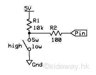
In order to prevent the floating of pin, resistors are added to the input circuits. The using of pull-up resistors are the most common method.
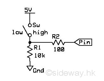
The other ways are the using of pull-down resistors.
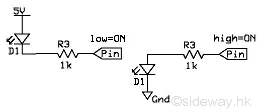
Digital OutputA simple application of digital output is turning a LED on or off. The digital output signal can be used to drive a LED circuit directly by changing the voltage level of the digital output pin at the interface circuitry.
CodeCode to test the combination of different types of digital inputs and outputs. HardwareHardware to examine the combination of different types of digital inputs and outputs.
Last Modified on 7/23/2010 |